Transient Analysis of RC Circuit
This tutorial is based on RC circuits with unit step Voltage and
current excitation. There will be separate tutorials based on RL
circuits. Gradually we shall build the concepts of transient analysis of
RC circuits with the help of problems.
The important equation you must remember is
$V_{C}(t)= V_{C}(\infty) +\left \{ V_{C}(0)-V_{C}(\infty) \right \}e^{-\frac{t}{\tau}} $
- For finite time constant capacitor does not allow a sudden change in voltage.
-
Once you find the circuit is of order 1, from the initial and final value you can get the behavior of the plot. Just any two points are connected exponentially. That’s it!
-
For a first-order circuit, every branch currents or node voltages (not only capacitor node) has a shape of an exponent.
-
To find out the order of any circuit, one needs to find out the degrees of freedom. Degrees of freedom of any circuit is the number of variables, needed to specify the initial condition of energy storage elements present in the circuit. (where input is not a variable though, remember!). Here energy the storage element is a capacitor.
-
In the case of steady-state, both the current and voltage must be constant with time. Now if we observe the voltage and current relation in a capacitor is,$i=c\frac{\mathrm{d} v}{\mathrm{d} t}$. To make both the current and voltage are to be constant, one the option is v=const and i=0 (not i=cons which will make v be changed linearly) which says the capacitor acts as an open circuit (i=0) in steady-state. Another way to say, the energy stored in a capacitor is $\frac{1}{2}CV^{2}$. Now energy is a physical quantity, so one can conclude that voltage across capacitor must be continuous(for the finite time constant circuit).
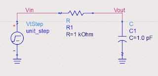
Initially, the capacitor is uncharged. So sudden change in the input will not affect the Vout node potential, rather all of it will be dropped across R. From this one can say initial Vout node potential 0V and initial current through R is (1-0)/1K = 1mA. Similarly, in the steady-state capacitor will act as an open circuit. Current through the resistor will be 0A and capacitor voltage will be 1V (all of the input).
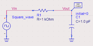
Now many times interviewer asks about the response of the low-pass filter for square wave excitation. In the question, they will mention the Time Period (T) of the square wave.
Before Answering one needs to keep in mind that, low pass filter suppresses the high-frequency signal. High-frequency harmonics present in the signal are attenuated by the low-pass filter. So we can solve the question with our concepts on RC time analysis, and the frequency of the behavior of the filter justifies it.
i) T >> RC = 1ns
i.e. Input frequency is very small. For f = 0.1 GHz the response is given below.
From a frequency domain point of view, the cut-off frequency is 1/(2*Pi*RC) = 0.159 GHz. So fundamental frequency of the signal passes well. Due to that output waveform resembles the input signal more or less. If we take the frequency of the signal very small compare to the cut-off frequency, the output will follow the signal more accurately.
ii)T= RC = 1ns
i.e. signal frequency is
1 GHz
RC low-pass filter is not an ideal filter. It attenuates the frequency component larger than the cut-off frequency by -20 dB/dec. In the above output, we see an attenuated version of the input. Interstinglingly one can point out the fact that it's working as an integrator. The reason behind this is an ideal integrator has Laplace transform of 1/S (a pole at origin), i.e. -20 dB/dec slope in the bode plot will give an integrating nature in the time domain. Quite interesting!
iii) T << RC = 1ns
i.e. signal frequency is
10 GHz
It also acts as an integrator due to the fact of the signal frequency is larger than the cut-off frequency. Here attenuation will be large as compared to the 1GHz signal due to the obvious reason. Above ripples can be suppressed by some other filter with a suitable cut-off frequency.
Initially, the capacitor is uncharged. So at t=0 when Vin has a jump of 1V, Vout also sees the same jump to keep the voltage across the capacitor the same as time t=0-. That is depicted in the bellow figure.
So initially all the voltage will drop across the resistor and will allow the maximum current to flow through the resistor which starts to charge the capacitor, hence VR= Vout = Vin - VC will decrease with time and this rate will be exponential. In the steady-state capacitor will be fully charged and acts as an open circuit. So no current flows through R and Vout node will be pulled down to 0V by the ground.
Initially, the capacitor is uncharged, at t=0 Capacitor acts as
short-circuit. At steady-state capacitor will be
open-circuited.
The time constant of the circuit is $(R_{1}+R_{2})C$ as Thevenin's resistance considering capacitor as load (open the cap and short the voltage source) is $R_{1}+R_{2}$. From the above data, we can draw the responses easily.
R in series with C adds a zero in the system, due to which we get a jump in the voltage at t=0. How to find all the poles and zeros from intuition will be discussed later. Also, the effect on the transient behavior will be discussed too.
4) 4)RC Low pass filter with series and parallel resistor
At t=0 capàshort-circuit ;steady state ,capà open-circuit
The thevenin's resistance of the circuit is\[(R_{1} || R_{3}))+R_{2}\] which can be evaluated by making the capacitor open and voltage source to be shorted. So the time constant of the circuit is \[\{(R_{1} || R_{3}))+R_{2}\}C\]


Thank you for the content. It is quite helpful for ECE students. The content is also presented in easy way which is easily understandable. Keep on doing more like this for more complex RLC circuit. Thank you.
ReplyDeleteThank you for your kind feedback. Sure I will try to cover all possible questions which can be asked in any Interview.
DeleteBravo! Nice effort
ReplyDeleteThank you.
DeleteAwesome this one as well.
ReplyDeleteThank you.
ReplyDeleteNice work. Simulations helps to correlate a lot
ReplyDeleteGreat work!! It is really helpful to understand the circuits in a different manner rather than using equations to solve them .. . Keep updating the pages for more complex RLC circuits. Thanks for putting up this kind of work
ReplyDeleteExcellent intuitive explanations! Please keep posting intuitions to analyze complex RLC networks. Thanks for the great content for aspiring analog engineers
ReplyDeleteVery nice content for freshers to get into the analog domain
ReplyDelete