In this tutorial most important interview questions on RC circuits will be
covered.
In this tutorial, we shall discuss questions on RC circuits which will be asked if you are appearing for an interview for the analog profile. It's asked to the candidates who are appearing for digital domain too. It's equally important for the ISRO, BARC, DRDO & ESE interviews.
If you observe the questions asked by the interviewer carefully have a pattern. The interviewer wants to hire the best candidate suitable for the profile. An interview continues on an average of 1-2 hours. But it's impossible for them to find out the best candidate for the role within that short span of time. So they ask a set of questions to judge your ability to think. So if you are able to incline your thoughts in that track, you have the upper hand in the interview.
1) Break your circuits into a number of nodes. Find out equivalent impedances in between those nodes. Try to do all the things in your mind only.
Now let's jump into the questions keeping the exact pattern set by an interviewer to judge your ability to think.
Always try to solve by yourself by your own method. Then check for the solution.
Interviewer:
Draw a circuit of two capacitors in series and apply unit-step voltage
to one end and take the output from the middle.
Your mind: easy! I can do that very easily.
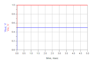
Voltage gets divided by the rule of a capacitive divider. No resistor connected, output will be reflected instantaneously.
\( V_{out} = V_{in} \times \frac{C_{1}}{C_{1}+C_{2}} \)
Result:
After this interviewer can ask for two things. I will list out both cases.
Case1
Interviewer: Connect a resistor in parallel with C2 and find the response again.
Your mind: Hold on a second, I can do that! But..........
Wait, is it a 1st order or a 2nd order circuit? I need to check the degrees of freedom! hmm....
Say initial voltage across \(C_{1}\) and \(C_{2}\) are \(V_{1}\) and \(V_{2}\) respectively.
\[V_{in}= V_{C2}+V_{C2}\]
So the degree of freedom is 1. Wow!
Now the job is easy.Now important nodes in the circuits are \(V_{in}\) and \(V_{out}\). At t=0 unit step changes its value instantaneously, which can be thought of as high frequency. For high-frequency capacitor acts as a short circuit.

|
| Schematic at t=0 |
At steady-state Vout is disconnected from Vin and Resistor R2 will pull down the Vout node to the ground.
Result: Now come to case 2 for 2nd question.Interviewer: Connect a resistor in parallel with C1 and find the response again.
Your mind: Is it inception or what! I know the trick already (LOL).
In the same manner, you say that the circuit is of order 1. At t=0 Vout potential is found by the capacitor divider rule. At steady-state, no current flows through R1, and the Vout node is shorted to the Vin node.

|
| Result |
After successfully answering the above two questions, you will be expecting one more question.
At t=0, the capacitors are dominant (as they act as a short circuit and I told you earlier to take the smaller one if they are in parallel).
At steady-state, the capacitors are open. Resistors will decide the Vout node potential.
case I: R1 C1 < R2 C2
R1C1< R2C2 implies, C1/(C1+C2) < R2/(R1+R2)
Initial value is less than final value.
Case II: R1 C1 = R2 C2
R1C1 > R2C2 implies, C1/(C1+C2) > R2/(R1+R2)
The initial value is greater than the final value.
Result:
Conclusions: Use the tricks of elements to consider. Also using the pole-zero concept and bode plot you can draw the transient behavior too. I will cover that part later on.


The blog looks awesome. I'll wait for your blog on intuitive study of poles and zeros in RC cirucits.
ReplyDeleteAs soon as I cover all RC topic and interview related questions on it ,I shall proceed for pole-zero concept.
Deletegood work Ashek.. It looks awesome.
ReplyDeleteThank you. Planning for some post on solving RL circuit too.
ReplyDeleteGreat wonderful
ReplyDeleteThank you very much!
DeleteAwesome Asek...well explained..I will request you to introduce inductors as well to take resonance in to consideration in transient analysis.
ReplyDeleteYes surja da I shall make some blogs on that.Thank you for the feedback.
ReplyDeleteAwesome blog..will provide a great insight to students preparing for VLSI interviews.👍
ReplyDeleteThank you for your wonderful feedback. It means a lot me.
ReplyDeleteAwesome and unparalleled work Ashek! We have a lot of complex mathematics based analog content but this intuitive work was very much needed to excel in the interviews. Congratulations to you and happy learning to us!
ReplyDeleteAwesome work guys!!
ReplyDeleteExcellent content for interview preparation.
God bless you guys for doing such novel work.
Waiting for your upcoming content.
Sir content is too good.Here I have a doubt, in case 1 , at t=0, why you applied voltage capacitive divison rule ,I think this formula applied only when capacitors are open circuited ,there I expecting Vout waveform like ,it raises for half time and decrease from next onwards , but it start decreases from 0.5 to 0 volts ,please explain this
ReplyDeleteYou need to consider dominating element. How do you tell one element is dominant? Here current is flowing through cap only (at t=0, a impulse input It's seeing and you know frequency domain of impulse is white kind of profile). So current is flowing through caps only, also you need to satisfy the KVL, which is determining the voltage across cap. So simply you apply the capacitive divider rule. And for steady no current flows through source which means voltage drop across res is 0. So o/p is zero.
DeleteExcellent work guys
ReplyDeleteexcellent.
ReplyDeletei have one suggestions if possible kindly share pdf of all this content so that it becomes easy to read