TEXAS INSTRUMENTS INTERVIEW QUESTIONS PART-2
Let's have an insightful discussion.
Solution:
This is a very basic question. It's asked to test your understanding of network theory. Immediately one should identify the fact that current through the 1K resistor is zero. Why so? Let me help you...
Here the circuit is partitioned into two parts. If circuit A provides a Current to circuit B through the 1K bridge resistor, there must be a path to accommodate the current from circuit B to A also. Due to the unavailability of a path to return the current, current through the bridge resistor is zero. Now the rest is easy.
Trick: When you try to find out the potential of any node from another node, the voltage will be added if you traverse from '-' to '+'.
Solution:
This is a special circuit. For a particular condition, it acts as a differential amplifier with an infinite common-mode rejection ratio.
At first, let me share the way I solved in the interview. Later on, I will give a complete overview of the circuit.
For an ideal op-amp, both the input nodes are virtually shorted. Due to infinite input resistance, op-amp allows no current at the input.
Consider
\[V^{+}=V^{-}=V_{A}\]
Assume the current direction through the resistor connected in between the positive terminal and the ground is downward. The direction of current through other resistor are shown accordingly. The voltage drop across the resistors is the same for all the resistors.
\[V^{-}=V^{+}+V_{A}+1+V_{A}\]
\[=>V_{A}=-0.5=V^{-}\]
now,
\[=>V{out}=V^{-}+V_{A}=-0.5-0.5=-1\]
Now come to the specialty of the circuit.
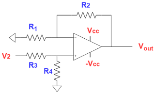
Take the
below circuit
If we apply the superposition theorem to solve this circuit. First V2=0.
Applying inverting amplier gain formula
\[V_{out,V1}=-\frac{R_{2}}{R_{1}} \times V_{1}\]
Consider V1=0
Applying non-inverting gain formula
\[ V_{out,V2}=\frac{R_{4}}{R_{3}+R_{4}}\times (1+ \frac{R_{2}}{R_{1}}) \times V_{2}\]
Consider the condition R2/R1 = R4/R3
\[V_{out,V2}=\frac{R_{2}}{R_{1}} \times V_{2}\]
For the above condition
\[ V_{out}=V_{out,V1}+V_{out,V2}=\frac{R_{2}}{R_{1}} \times (V_{2}-V_{1})\]
In our case (V2-V1)= -1V so, Vout = -1V
If you have any doubt, let me know in the comment section. For other tutorials check INDEX. For further updates follow my blog (rlcanalog.blogspot.com). The blog is specially made for GATE and VLSI aspirants (ANALOG INTUITION ( GATE & VLSI)).


No comments:
Post a Comment