Texas Instruments Interview Experience
TI Analog Interview Question
The wait is over now. I'm going to share my interview experience in Texas
Instrument held on 2nd December 2020. Luckily I'm going to join TI (Analog
Engineer) in a month or so. I was selected in analog as well as digital profiles after the written test conducted by TI. There were a total of five rounds, which I had to clear. First, they took the written test. There were 3 sections consisting of 20 questions each. The sections were "aptitude, analog and digital
". There was a section for embedded systems too which I didn't opt for.
On the interview day, I gave four interviews. Two of them were for 'Analog
profile'. One was for 'Digital profile' which held in between those two.
they asked me my preference on the profile and I chose 'Analog'. At last,
there was one hr round.
They asked me 8 or 9 questions in the two rounds of analog interviews.
Three questions from the RLC circuit (one RC, one RL, and one RLC). Also three from the switch-capacitor (diode) circuits. Some questions asked from the Mtech. project too.
So let's jump into my interview experience and the questions they asked. I will try to cover it in three separate posts.
1st round Analog:
Q1)
Find out the waveform of
\(I) V_{out}\)
\(II) I_{C1}\)
\(II) I_{R}\)
\(IV) I_{C2}\)
Solution: The concepts you need to know before you make an attempt to solve this question. Click Here
Here, you can easily predict the waveform of \(Vout(t=0) = C1/(C1+C2)\) and
\(Vout(t= \infty ) = 0\). Also \(I_{R}= Vout/R\).
Now coming to capacitor currents, initially, the response is an impulse. The area under the impulse is C1C2/(C1+C2). As you know \(i= C\frac{\mathrm{d} V}{\mathrm{d} t}\), here C= series combination of
C1 and C2. V is unit-step function.
Similarly at steady-state current is zero for both capacitors. I've found a mismatch of the capacitor currents in between the simulation output and the IFT analysis. Though our predictions about the terminal values are correct. The interviewer asked about the initial and final value of the currents only. Let me know the reason in the comment section.
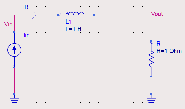
Q2) Predict the output waveforms of the below circuit.
Solution:
Well, the circuit is just like charging an inductor with a current source. The inductor will allow the sudden change in current adjusting the voltage drop across it. Before we predict the Vin, let's find out, how does Vout look like? Well, a resistor never fights with the current flows through it. So Vout = I*R, which is shown.
Now Voltage across the inductor is an impulse having a magnitude of L
as \[V_{L}= L\frac{\mathrm{d} I}{\mathrm{d} t}\]
Now\[V_{in}= V_{out}+V_{L}\]
The above two equations justify the behavior of Vin.
Q3)Find out the output wave-form Vout. The initial voltage across
the capacitor is 1V.
Solution:
Well, this can be solved using multiple methods.
But consider the fact that at t =0 inductor experiences two unit step
voltages at both terminals. The voltage drop across the inductor is
zero. \(V_{L}=L \times \frac{\mathrm{d} i}{\mathrm{d} t}\). So for zero
inductor voltage, the current is constant. Current is zero as initially,
the current was zero. There is no way to charge the capacitor. Hence no way to control the dynamic behavior of the inductor. Capacitor will hold its charge.
If you have any doubt, let me know in the comment section. For other tutorials check INDEX. For further updates follow my blog (rlcanalog.blogspot.com). The blog is specially made for GATE and VLSI aspirants (GATE Electronics( GATE & VLSI)).


The current output is correct in simulation for question 1.If you see the y axis, the current is in Mega Amperes because of the high impulse. If you change the y axis units to -1 to 1 Ampere, you will see the decaying nature of currents in both capacitor currents.
ReplyDeleteYes you are correct.
DeleteYour blogs are very helpful. Please keep posting more topics. Thanks!
Delete