Showing posts with label Analog interview. Show all posts

INTRINSIC GAIN METHOD EX-1

FINDING GAIN OF DEGENERATED & CASCODE AMPLIFIER 


In this post, we shall discuss two basic amplifiers. 

Q1) Find the gain.


Solution: 

From the signal flow, it is evident that the amplifier is in CS mode.
Let's directly write the gain expression. What is the Intrinsic Gain Method

$GAIN=V_{IN} \times \frac{R_{LOAD}}{R_{LOAD}+R_{OUT}}$

Now, ${R_{LOAD}=R_{D}}$ ; ${R_{OUT}=r_{0}+M \times R_{S}}$, where $M= 1+g_{m}r_{0}$

How did I write the above expression? Go check.
$GAIN= -g_{m}r_{0} \times \frac {R_{D}}{R_{D}+(r_{0}+M \times R_{S})} \approx -g_{m}r_{0}\times \frac {R_{D}}{M \times R_{S}} \approx -\frac{R_{D}}{R_{S}}$

Let's try to solve it by another method called, $G_{m}r_{out}$ method and match the results with the above result.


Another Method: 

We know the equivalent transconductance of the source-degenerated CS is $G_{M}= - \frac {g_{m}}{1+g_{m}R_{S}}$

$R_{eq}=R_{LOAD} || R_{OUT} \approx R_{D}$

$GAIN=G_{M}R_{eq}=- \frac {g_{m}}{1+g_{m}R_{S}} \times R_{S}$

Considering, $g_{m}R_{S}>>1$

$GAIN \approx -\frac{R_D}{R_S}$, which matches with the previous result.


Q2) Find the gain.


Solution: Let's draw the schematic for a small signal.


The above diagram shows that M1 and M2 are in CS and CG mode respectively. 
$GAIN= -g_{m1}r_{01} \times M_{2} \times \frac {R_{LOAD}}{R_{LOAD}+R_{OUT}}$
 where, $R_{LOAD}= r_{03}+M_3 \times r_{04} \approx M_3 \times r_{04}$
             $R_{OUT}= r_{02}+M_2 \times r_{01} \approx M_2 \times r_{01}$ 
Now,
The $GAIN= -g_{m1} \times \frac {M_{2} \times r_{01} \times R_{LOAD}}{R_{LOAD}+R_{OUT}}$ =$-g_{m1}(R_{LOAD}|| R_{OUT})$

Let's also try with  $G_{m}r_{out}$ method.


Another Method: 


$\frac{I_{SC}}{V_{IN}}= G_{M}=-g_{m1} \frac {r_{01}}{\frac{1}{g_{m2}}+r_{01}} \approx -g_{m1}$


$GAIN=G_MR_{eq}=-g_m \left(R_{LOAD}||R_{OUT} \right)$, which matches with above result.


We will solve more complex circuits in the upcoming posts.
Check previous posts of the series we started "INTRINSIC GAIN METHOD".

PART1: INTRINSIC GAIN METHOD
PART2: INTRINSIC GAIN METHOD PARAMETERS 
PART3: FINDING EQUIVALENT IMPEDANCE

For part 5 follow our blog and don't forget to comment


Fundamental Concept Of Differential Amplifier

This post is going to deal with a very basic concept of differential amplifier. What I personally feel is that, not many students are clear about the virtual ground/ half circuit concept in diff amp. Textbooks will make the half  circuit and simply find the gain, which is the root of the problem. But remember, always go with the basics. So, personally I would prefer to write 5 extra lines instead of the half circuit approach and you will find its worth when you come across the 2nd problem of this post.


Before starting let me tell you the convention. I have used Capital Letters for DC and Small letters for AC. Suppose $V_{out}=V_{OUT}+v_{out}$ where $V_{OUT}$ is the common mode value and $v_{out}$ is the small signal value.


I shall start this post with a very simple and common question. Let's consider the following circuit of Fig:1(a). Let's try to find the differential gain $A_{dm}$ and common mode gain $A_{cm}$. Ignore $g_{ds}$. Take $g_m$ of M1= $g_m$


Let's start with DC analysis, by applying a common voltage of $V_{CM}$ at the gate of M1 and M2. As the gates have same potential and the sources are shorted, hence $V_{GS1}=V_{GS2}$. Also $(W/L)_1=(W/L)_2$. So, the bias current $I_B$ will divide in 1:1 ratio, hence M1 and M2 will carry a current of $\frac{I_B}{2}$. 

$V_{OUT1}=V_{OUT2}=V_{DD}-\frac{I_BR}{2}$

Hence, $A_{cm}=\frac{V_{OUT1}-V_{OUT2}}{VCM}=0$

Now, $g_m=\mu_nC_{ox}\frac{W}{L}\left(V_{GS}-V_{TH}\right)$
So, $g_{m1}=g_{m2}$


Now, let's jump to the ac analysis by applying $+\frac{vin}{2}$ at the gate of M1 and $-\frac{vin}{2}$ at the gate of M2. The $V_{DD}$ is ac grounded and also the $I_B$ is opened as these sources won't change small signal wise.

Let's try to find out what will happen to the $v_x$ small signal wise. Applying KCL at $v_x$,

$g_{m1}v_{gs1}+g_{m2}v_{gs2}=0$
$g_m\left(\frac{v_{in}}{2}-v_x\right)+g_m\left(-\frac{v_{in}}{2}-v_x\right)=0$
$v_x=0$

So, the $v_x$ node won't move small signal wise. Hence, $v_x$ will be at ac ground.

So, $i_1=g_m\frac{v_{in}}{2}  => v_{out1}=-i_1R=-g_mR\frac{v_{in}}{2}$
      $i_2=-g_m\frac{v_{in}}{2} => v_{out2}=-i_2R=g_mR\frac{v_{in}}{2}$

Hence, $A_{dm}=\frac{v_{out1}-v_{out2}}{v_{in}}=-g_mR$


Now, let me make a small change in this circuit with the same question. Let's try to find the differential gain $A_{dm}$ and common mode gain $A_{cm}$ of Fig:2(a). Ignore $g_{ds}$. Take $g_m$ of M1= $g_m$. (First give it an honest try without seeing the solution)


Let's start with DC analysis, by applying a common voltage of $V_{CM}$ at the gate of M1 and M2. As the gates have same potential and the sources are shorted, hence $V_{GS1}=V_{GS2}$. But, $(W/L)_2=5(W/L)_1$. So, the bias current $I_B$ will not divide in 1:1 ratio in this case.

Assuming square law is valid,

$I_1=\frac{\mu_nC_{ox}}{2}\frac{W}{L}\left(V_{GS}-V_{TH}\right)^2$
$I_2=\frac{\mu_nC_{ox}}{2}\frac{5W}{L}\left(V_{GS}-V_{TH}\right)^2$

So, $I_1=\frac{I_B}{6}$ and $I_2=\frac{5I_B}{6}$

$V_{OUT1}=V_{DD}-I_1\left(5R\right)=V_{DD}-\frac{5I_BR}{6}$
$V_{OUT2}=V_{DD}-I_2R=V_{DD}-\frac{5I_BR}{6}$

Hence, $A_{cm}=\frac{V_{OUT1}-V_{OUT2}}{VCM}=0$

Now $g_m=\mu_nC_{ox}\frac{W}{L}\left(V_{GS}-V_{TH}\right)$
So, $g_{m2}=5g_{m1}$

Now, let's jump to the ac analysis by applying $+\frac{vin}{2}$ at the gate of M1 and $-\frac{vin}{2}$ at the gate of M2. The $V_{DD}$ is ac grounded and also the $I_B$ is opened as these sources won't change small signal wise.

Let's try to find out what will happen to the $v_x$ small signal wise. Applying KCL at $v_x$, 


$g_{m1}v_{gs1}+g_{m2}v_{gs2}=0$
$g_m\left(\frac{v_{in}}{2}-v_x\right)+5g_m\left(-\frac{v_{in}}{2}-v_x\right)=0$
$v_x=-\frac{v_{in}}{3}$

So, the $v_x$ node will move small signal wise. Hence, $v_x$ will not be at ac ground.

So, $i_1=g_{m1}v_{gs1}=g_m(\frac{v_{in}}{2}+\frac{v_{in}}{3})=\frac{5g_mv_{in}}{6}$ 
$\Rightarrow v_{out1}=-i_1\left(5R\right)=-\frac{25g_mRv_{in}}{6}$

$i_2=g_{m2}v_{gs2}=5g_m(-\frac{v_{in}}{2}+\frac{v_{in}}{3})=-\frac{5g_mv_{in}}{6}$ 
$\Rightarrow v_{out2}=-i_2R=-\frac{5g_mRv_{in}}{6}$


Hence, $A_{dm}=\frac{v_{out1}-v_{out2}}{v_{in}}=-5g_mR$


Now, you may get a small doubt here. Suppose, you are applying the virtual ground (which is indeed wrong) and you have 2 half circuits.

For the left half circuit, $v_{out1}=-g_m\left(5R\right)\frac{v_{in}}{2}$
For the right half circuit, $v_{out2}=-5g_m\left(R\right)\frac{-v_{in}}{2}$

So, $A_{dm}=\frac{v_{out1}-v_{out2}}{v_{in}}=-5g_mR$ which is matching with the answer. But I would like to say, it's not the right way as your assumption of virtual ground is completely wrong. But it's also important to know, then why is it giving the right answer? Let's find out. For that, we have to know, whether the differential gain depends on the value of $v_x$ or not.

$i_1=g_{m1}v_{gs1}=g_m\left(\frac{v_{in}}{2}-v_x\right)$ 
$\Rightarrow v_{out1}=-i_1\left(5R\right)=-\left(5R\right)g_m\left(\frac{v_{in}}{2}-v_x\right)$

$i_2=g_{m2}v_{gs2}=5g_m\left(-\frac{v_{in}}{2}-v_x\right)$
$\Rightarrow v_{out2}=-i_2\left(R\right)=-\left(5R\right)g_m\left(-\frac{v_{in}}{2}-v_x\right)$

$v_{out1}-v_{out2}=-\left(5R\right)g_m\left(\frac{v_{in}}{2}-v_x\right)+\left(5R\right)g_m\left(-\frac{v_{in}}{2}-v_x\right)$
$\Rightarrow v_{out1}-v_{out2}=-5g_mRv_{in}+5Rv_x-5Rv_x=-5g_mRv_{in}$

So, basically the terms containing $v_x$ are cancelling each other, that's why the differential gain is not depending on the value of $v_x$. But for dc wise imbalanced circuit, it won't happen and the answer will be wrong if you consider $v_x$ as virtual ground.


I hope, next time you won't face any confusion related to half circuit analysis or virtual ground. Happy learning.

How to Prepare for Texas Instruments Analog Profile

How to Prepare for Texas Instruments Analog Profile


Texas Instruments has been making progress possible for decades. TI is a global semiconductor company that designs, manufactures, tests, and sells analog and embedded processing chips. Their approximately 80,000 products help over 100,000 customers efficiently manage power, accurately sense and transmit data and provide the core control or processing in their designs, going into markets such as industrial, automotive, personal electronics, communications equipment, and enterprise systems. Their passion to create a better world by making electronics more affordable through semiconductors is alive today as each generation of innovation builds upon the last to make our technology smaller, more efficient, more reliable, and more affordable – opening new markets and making it possible for semiconductors to go into electronics everywhere. They think of this as Engineering Progress. It’s what they do and has been doing for decades.  


TI also has a Digital domain, but in this blog, we shall discuss mainly the Analog domain and the preparation strategy to crack it. If you love Analog, Microelectronics, Devices then TI is one of the best places to work and learn. TI has an awesome work culture.


Recruitment Procedure 

TI has a fixed procedure for the job as well as for the internship.

  1. Online test: It consists of 20 aptitude questions in 20 minutes and 20 technical questions (depending upon profile) in 30 minutes. 
  2. Technical interview: 1/2 rounds of Pure Technical interview. The interview will be more interactive. They will fully cooperate with you and will give you hints if you are stuck at some point.
  3. Human Resource - HR interview: (General question) about yourself, why not Higher Studies? Why TI? What are your strengths and weakness?
You are almost selected if you have reached till HR round unless you screw up big time.

TI Job Profiles

Let's have a look on the job profiles offered in TI for Analog Domain. In Analog, you will work in:
  • Audio
  • Energy automation
  • Electronic point of service
  • Industrial automation
  • Imaging
  • High speed
  • Interface
  • Clocking
  • Medical
  • High volume linear
  • Storage
  • Power supply
  • Linear power
  • Battery management


How to prepare for the Online Test & Technical Interview for internship/ job in TI? 

First let's hear from them 👇

1. PYQs 

2. Basic Network Theory (**Most Important**)

  • Basics of R,L, C
  • Step (voltage/current) response of 1st order RC/RL circuits (intuition method) [They keep on adding the components trying to make it complicated]
  • Pulse (voltage/current) response of 1st order RC/RL circuits (intuition method)
             * T >>RC

             * T <<RC

  • Finding pole/zero by inspection and draw bode plot (intuition method)
  • Charge sharing between capacitors (with and without initial condition)
  • Identification of type of Filters (LPF/HPF/BPF/BSF/APF)


3. Basic Analog Circuit 

  • Regulators
  • Barkhausen Condition & Positive feedback circuits (Oscillators, Multivibrators)
  • Standard OPAMP circuits 
  •     * Inverting Amplifier
        * Non-inverting Amplifier
        * Adder
        * Subtractor
        * Differentiator
        * Integrator  
  • Sign of input terminals of an OPAMP     
  • Analysis of OPAMP circuits with different non-idealities
             * finite open-loop gain
             * finite slew rate
             * finite BW
             * finite input & output resistance
             * finite input-referred offset voltage

  • Identification of Positive and Negative feedback
  • Circuits with multiple feedbacks and which feedback is dominant
  •     

      4. Control System

      • Bode plot (relation between dc gain, gain at infinite frequency, and number of pole-zero)
      • Stability (Gain Margin, Phase Margin, Gain crossover frequency, Phase crossover frequency)


      5. Microelectronic Circuit

      • Basic working principle, I-V characteristics and various region of operation of diode, BJT, MOSFET
      • Gain of different MOSFET(or BJT) based amplifiers (intuition method without small signal model)
                   * CS
                   * CG
                   * CD
                   * Cascade
                   * Cascode
      • Looking in impedance at any node of a MOS/BJT circuit (intuitively without small signal model)
      • Different architectures of current mirrors and headroom of each transistor
      • Differential amplifier with passive and active load, Differential gain and Common-mode gain, CMRR
      • Internal transistor-level circuit of an OTA (Operational Transconductance Amplifier)
      • Different architectures of OTA and pole zeroes
                   * Simple 5T OTA (DC Gain, Pole-zero, UGB, PM, ICMR, Output swing, PSRR)
                   * Telescopic
                   * Folded Cascode
                   * Regulated Cascode
      • 2 stages OTA with Miller compensation and dominant pole
      • Noise and Mismatch (current mirror and diff pair) analysis

      7. Signals & Systems (Not that important)

      • Basics of LTI systems
      • Convolution
      • Frequency domain- CT, DT, DTFT, DFT

      8. Switch Capacitor circuits with two non-overlapping clocks


      Where to study from? What are the available resources? 

      1. Online Video Lectures:

      2. Online Blog:

      3. TI Official PPT:

      4. Books:


      Important: We tried to make this blog very compact and neat. If you want to pursue a career in the analog industry, you must go through the above material. If you find any material which is not listed here and that might help readers, please let us know. Do comment and for further queries, you can mail us at rlcanalog@gmail.com.

      If you have any doubt, let me know in the comment section. For other tutorials check INDEX
      For further updates follow my blog (rlcanalog.blogspot.com). 
      For Better reach, Search "Analog Intuition Blog" on google. 

      TEXAS INSTRUMENTS

      TEXAS INSTRUMENTS INTERVIEW QUESTIONS PART-2

      In the last post, I discussed my interview experience. In this post, I shall take forward that discussion. 
      The interviewers asked some basic questions on network theory and op-amp which mostly asked to a 3rd year BTech. student, applying for the internship.
      Let's have an insightful discussion.


      Q4)

      Solution: 

      This is a very basic question. It's asked to test your understanding of network theory. Immediately one should identify the fact that current through the 1K resistor is zero. Why so? Let me help you...


      Here the circuit is partitioned into two parts. If circuit A provides a Current to circuit B through the 1K bridge resistor, there must be a path to accommodate the current from circuit B to A also. Due to the unavailability of a path to return the current, current through the bridge resistor is zero. Now the rest is easy.


      So \[V{x}= 0+2+0-3=-1V\]

      Trick: When you try to find out the potential of any node from another node, the voltage will be added if you traverse from '-' to '+'.


      Q5) 


      Solution:

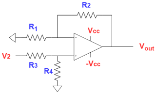
      This is a special circuit. For a particular condition, it acts as a differential amplifier with an infinite common-mode rejection ratio.

      At first, let me share the way I solved in the interview. Later on, I will give a complete overview of the circuit.

      For an ideal op-amp, both the input nodes are virtually shorted. Due to infinite input resistance, op-amp allows no current at the input

      Consider 

      \[V^{+}=V^{-}=V_{A}\]


      Assume the current direction through the resistor connected in between the positive terminal and the ground is downward. The direction of current through other resistor are shown accordingly. The voltage drop across the resistors is the same for all the resistors.

      \[V^{-}=V^{+}+V_{A}+1+V_{A}\]

      \[=>V_{A}=-0.5=V^{-}\]

      now,

      \[=>V{out}=V^{-}+V_{A}=-0.5-0.5=-1\]

      After that interviewers asked whether my assumption for the direction of the current is correct or not? In reply, I said no.

      Now come to the specialty of the circuit. 
      Take the below circuit


        If we apply the superposition theorem to solve this circuit. First V2=0.


      \(V^{+}=0=V^{-}\) 

      Applying inverting amplier gain formula

      \[V_{out,V1}=-\frac{R_{2}}{R_{1}} \times V_{1}\]

      Consider V1=0

      Applying non-inverting gain formula

      \[ V_{out,V2}=\frac{R_{4}}{R_{3}+R_{4}}\times (1+ \frac{R_{2}}{R_{1}}) \times V_{2}\]

      Consider the condition R2/R1 = R4/R3

      \[V_{out,V2}=\frac{R_{2}}{R_{1}} \times V_{2}\]

      For the above condition

      \[ V_{out}=V_{out,V1}+V_{out,V2}=\frac{R_{2}}{R_{1}} \times (V_{2}-V_{1})\]

       In our case (V2-V1)= -1V so, Vout = -1V


      Previous Page                           Index              


      If you have any doubt, let me know in the comment section. For other tutorials check INDEXFor further updates follow my blog (rlcanalog.blogspot.com). The blog is specially made for GATE and VLSI aspirants (ANALOG INTUITION ( GATE & VLSI)).


      Transient Analysis of RC Circuit

       Transient Analysis of RC Circuit

      This tutorial is based on RC circuits with unit step Voltage and current excitation. There will be separate tutorials based on RL circuits. Gradually we shall build the concepts of transient analysis of RC circuits with the help of problems.

         The important equation you must remember is 

      $V_{C}(t)= V_{C}(\infty) +\left \{ V_{C}(0)-V_{C}(\infty) \right \}e^{-\frac{t}{\tau}} $

      • For finite time constant capacitor does not allow a sudden change in voltage.

      •        Once you find the circuit is of order 1, from the initial and final value you can get the behavior of the plot. Just any two points are connected exponentially. That’s it!

      •    For a first-order circuit, every branch currents or node voltages (not only capacitor node) has a shape of an exponent.

      •    To find out the order of any circuit, one needs to find out the degrees of freedom. Degrees of freedom of any circuit is the number of variables, needed to specify the initial condition of energy storage elements present in the circuit. (where input is not a variable though, remember!). Here energy the storage element is a capacitor.

      •        In the case of steady-state, both the current and voltage must be constant with time. Now if we observe the voltage and current relation in a capacitor is,$i=c\frac{\mathrm{d} v}{\mathrm{d} t}$. To make both the current and voltage are to be constant, one the option is v=const and i=0 (not i=cons which will make v be changed linearly) which says the capacitor acts as an open circuit (i=0) in steady-stateAnother way to say, the energy stored in a capacitor is $\frac{1}{2}CV^{2}$. Now energy is a physical quantity, so one can conclude that voltage across capacitor must be continuous(for the finite time constant circuit). 


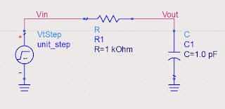
          1) RC Low Pass


      Initially, the capacitor is uncharged. So sudden change in the input will not affect the Vout node potential, rather all of it will be dropped across R. From this one can say initial Vout node potential 0V and initial current through R is (1-0)/1K = 1mA. Similarly, in the steady-state capacitor will act as an open circuit. Current through the resistor will be 0A and capacitor voltage will be 1V (all of the input).


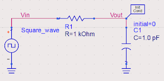
      Now many times interviewer asks about the response of the low-pass filter for square wave excitation. In the question, they will mention the Time Period (T) of the square wave.


      Before Answering one needs to keep in mind that, low pass filter suppresses the high-frequency signal. High-frequency harmonics present in the signal are attenuated by the low-pass filter. So we can solve the question with our concepts on RC time analysis, and the frequency of the behavior of the filter justifies it.


      i) T >> RC = 1ns 

      i.e. Input frequency is very small. For f = 0.1 GHz the response is given below.

      From a frequency domain point of view, the cut-off frequency is 1/(2*Pi*RC) = 0.159 GHz. So fundamental frequency of the signal passes well. Due to that output waveform resembles the input signal more or less. If we take the frequency of the signal very small compare to the cut-off frequency, the output will follow the signal more accurately. 


      ii)T= RC = 1ns
      i.e.  signal frequency is 1 GHz


      RC low-pass filter is not an ideal filter. It attenuates the frequency component larger than the cut-off frequency by -20 dB/dec. In the above output, we see an attenuated version of the input. Interstinglingly one can point out the fact that it's working as an integrator. The reason behind this is an ideal integrator has Laplace transform of 1/S (a pole at origin), i.e. -20 dB/dec slope in the bode plot will give an integrating nature in the time domain. Quite interesting!


      iii) T << RC = 1ns
      i.e.  signal frequency is 10 GHz


      It also acts as an integrator due to the fact of the signal frequency is larger than the cut-off frequency. Here attenuation will be large as compared to the 1GHz signal due to the obvious reason. Above ripples can be suppressed by some other filter with a suitable cut-off frequency.


      2) RC High pass

      Initially, the capacitor is uncharged. So at t=0 when Vin has a jump of 1VVout also sees the same jump to keep the voltage across the capacitor the same as time t=0-. That is depicted in the bellow figure.

      So initially all the voltage will drop across the resistor and will allow the maximum current to flow through the resistor which starts to charge the capacitor, hence VR= Vout = Vin - VC  will decrease with time and this rate will be exponential. In the steady-state capacitor will be fully charged and acts as an open circuit. So no current flows through R and Vout node will be pulled down to 0V by the ground. 


      3)   Low pass filter with series resistance

      Initially, the capacitor is uncharged, at t=0 Capacitor acts as short-circuit. At steady-state capacitor will be open-circuited.

      The time constant of the circuit is $(R_{1}+R_{2})C$ as Thevenin's resistance considering capacitor as load (open the cap and short the voltage source) is $R_{1}+R_{2}$. From the above data, we can draw the responses easily.

      R in series with C adds a zero in the system, due to which we get a jump in the voltage at t=0. How to find all the poles and zeros from intuition will be discussed later. Also, the effect on the transient behavior will be discussed too.


      4) 4)RC Low pass filter with series and parallel resistor 

      At t=0 capàshort-circuit ;steady state ,capà open-circuit


      The thevenin's resistance of the circuit is\[(R_{1} || R_{3}))+R_{2}\] which can be evaluated by making the capacitor open and voltage source to be shorted. So the time constant of the circuit is \[\{(R_{1} || R_{3}))+R_{2}\}C\]